
AVR Based Alarm Clock
 Not being satisfied with just a plain boring digital or analogue alarm clock, I decided to create one myself. What I wanted was a white backlight LCD screen with large numbers that weren't in the usual 7 segment format. As for features it had to of course show the time, have an alarm, have that alarm be able to be set to which day of the week it goes off on, read the room temperature, read the room humidity, have a pleasant alarm sound, and be easy to set. What I ended up creating has all of those features, plus a few more. Read on...
This was my first ever micro controller based project. I have had a bit of a tinker with AVR's when I had one as a Hotchip. This was a little 40 pin module with a AT90S8535 on it, along with a RTC and serial driver. It could be programmed with a quite unreliable BASIC programming language and downloader. After a little search on the web I found Bascom AVR, and purchased a copy of that. Bascom AVR is a BASIC compiler for the AVR family of RISC controllers and it comes with libraries to drive all manner of peripheral devices to your micro controller, including one to drive KS0108 based displays. That display driver was handy as that is the heart of the AVR based alarm clock. I started off programming the Hotchip board for an early prototype and to test Bascom and the display library out. But my code soon exceeded the memory of the AT90S8535. I switched to a ATMega16, but ran out of memory on that too. I ended up using a ATMega32 running on its own internal clock of 8MHz. I find it quite nifty that the alarm clock I built is running on a processor that seems more powerful than my first computer! (A Commodore 16).
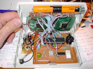
Below you can see a picture of the clock on the breadboard in its prototype state.
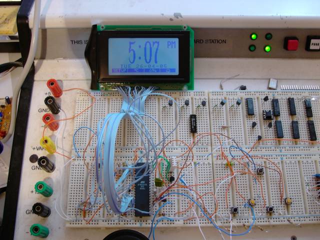
All the IC's in the top right corner have nothing to do with the clock, they are just sitting there from previous projects. The main guts is in the bottom left corner of the picture, with the buttons to control it in the bottom right. The button that's a bit higher up is the snooze button.
The next two pictures shows a close up of the two white LED's I mounted to the display on the left and a close up shot of the display on the right.
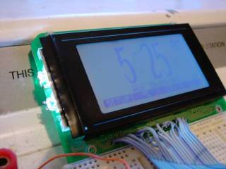
The display was originally backlit with an array of green surface mount LED's but the original equipment that this display came out of used a 24v line to drive the backlight. As I wanted my clock to work off 5 volts that was out of the question. By sacrificing a larger 320x128 backlit display I used the light guide and side mounted the two white LED's to give it its nice blue/white appearance.
Bascom has a "Showpic" statement which I used to display the large characters. The characters were made using a fancy font in photoshop, trimmed to be all equal size and saved as BMP bitmaps, the other graphics were mainly drawn in Microsoft Paint. Bascom has a little conversion utility to convert these into raw data that is used with the showpic statement. The "PM" Icon is a picture as well with the same dimensions as the numbers. I can fit 8 numbers/letters across the display with a normal 8x8 font underneath and 8x128 pixel menu bar which is also a picture using the showpic statement.
Once we had the basic functions working and after finding a suitable enclosure, we moved the project off the breadboard and into strip board or Veroboard. Yes an etched board would have been nicer, but I didn't have the facilities to etch at the time.
Below are two pictures, one showing the display side of things and the other the control side of things. You'll note two AA size NiMh in the pictures. They provide power for when there is a power cut. During a power cut, the display backlight is turned off, but all other functions keep going, even the alarm will go off in a blackout! :-)
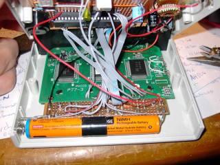
You can also see the little inverter kit that I got from Jaycar to regulate the power and keep the batteries on trickle.
Here is a larger image of the control side of things:
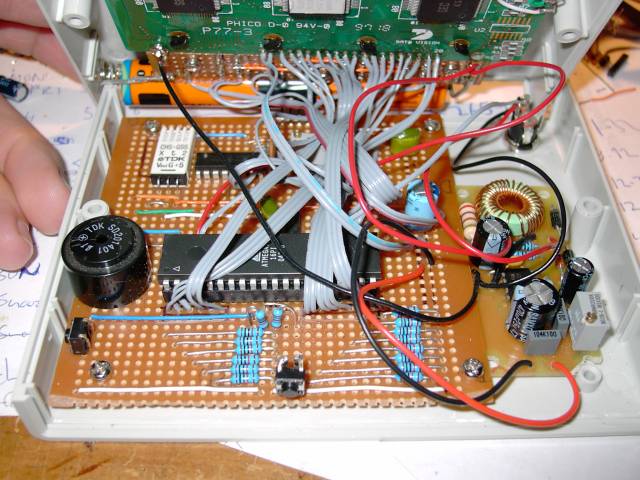
On this image you can see the inverter to the right, and the snooze button in the bottom middle. The beeper to the left and the reset button just below it. In the top left you can see the humidity sensor which has the LM35 temperature sensor mounted below it on the other side of the board.
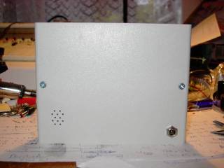
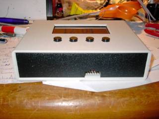
The enclosure is a simple flat plastic case from Jaycar which I am using stood upright. I cut a hole in one side to fit the display and glued PCB spacers into to mount the display and push-button board. For the snooze button I decided to use the entire top (which would otherwise be a front or rear panel) and filed down the long sides to that it can pivot slightly on the shorter sides. It worked better than I expected as you can pretty much push the top anywhere along its width and activate the snooze. Pushing the snooze twice quickly will disable the alarm for that day.
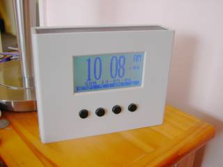
These three pictures show the finished clock in its case. In the middle picture you can see the little vents I drilled for the humidity and temperature sensors and the picture on the right shows the programming connector on the bottom.
.jpg)
Once it was all enclosed I fine tuned the code and added some extra features. these are explained below:
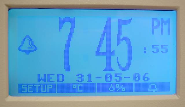
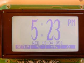
Here you see a close up of the normal display mode, showing the time, date and that the alarm is set. The four buttons are "Soft keys", that is, their functions change depending on what mode the clock is in. The Colon ':' between the numbers flashes on and off once per second.
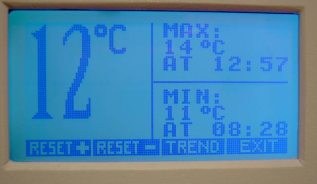
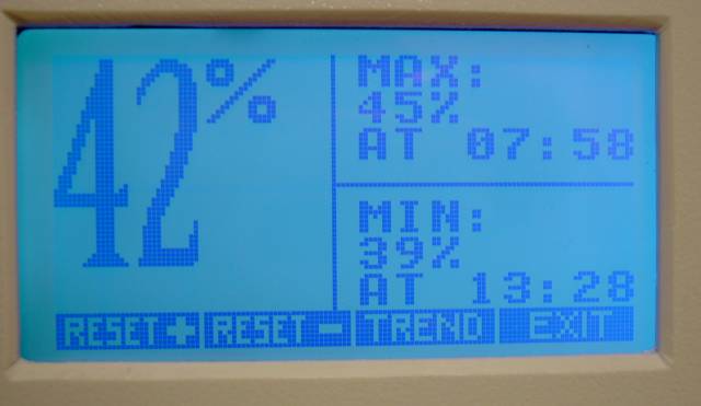
Pressing the second button in from the left will show you the current room temperature and minimum and maximum for that day. : (it's a bit cold)
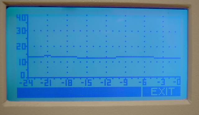
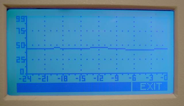
Pressing the button labelled 'Trend' will give you a trend of the temperature over the last 24 hours:
The same goes for the humidity function:
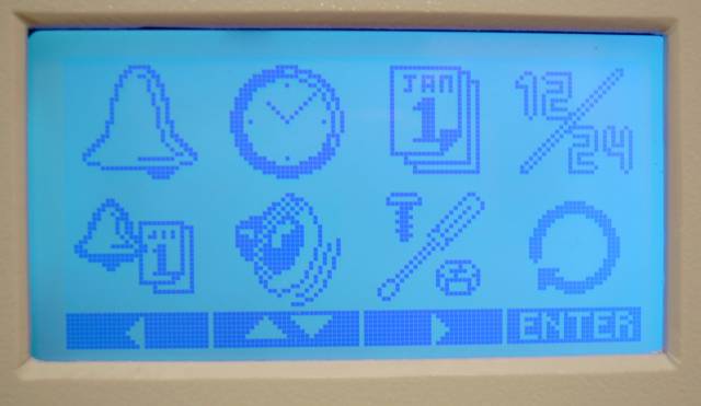
Setting the initial time, date and alarm time is easily achieved by pressing the 'setup' button from the main screen. You can then use the up, down, left and right buttons to select which function you want to set:
The functions selectable are (from left to right, top to bottom), Set Alarm, Set Time, Set Date, 12 or 24 hour mode, Set days alarm goes off on, turn key beep on or off, extra fiddle menu and return to main screen
To set the days on which the alarm goes off on, one selects the bottom left icon and presses enter:
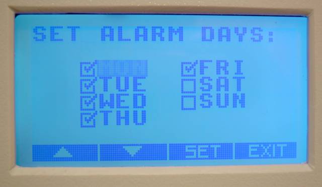
here you can scroll thru the days and tick or un-tick as desired. No more forgetting to set the alarm on a Monday or being woken up at 6:30 on a Saturday morning!
All up I am very happy with the outcome of this project, It hasn't missed a beat yet and wakes me up every weekday. I have since added a function too that automatically dims the display when there is low ambient light so as not to light the room up with its backlight. I still need to write some code to be able to adjust the switch point as at the moment it is fixed and a wee bit off the mark, as in when its dusk, the display can be a bit hard to see. Another feature I would like to add is being able to program all the public holidays in with a computer and download them to the clock so one never has to set the alarm on or off again.
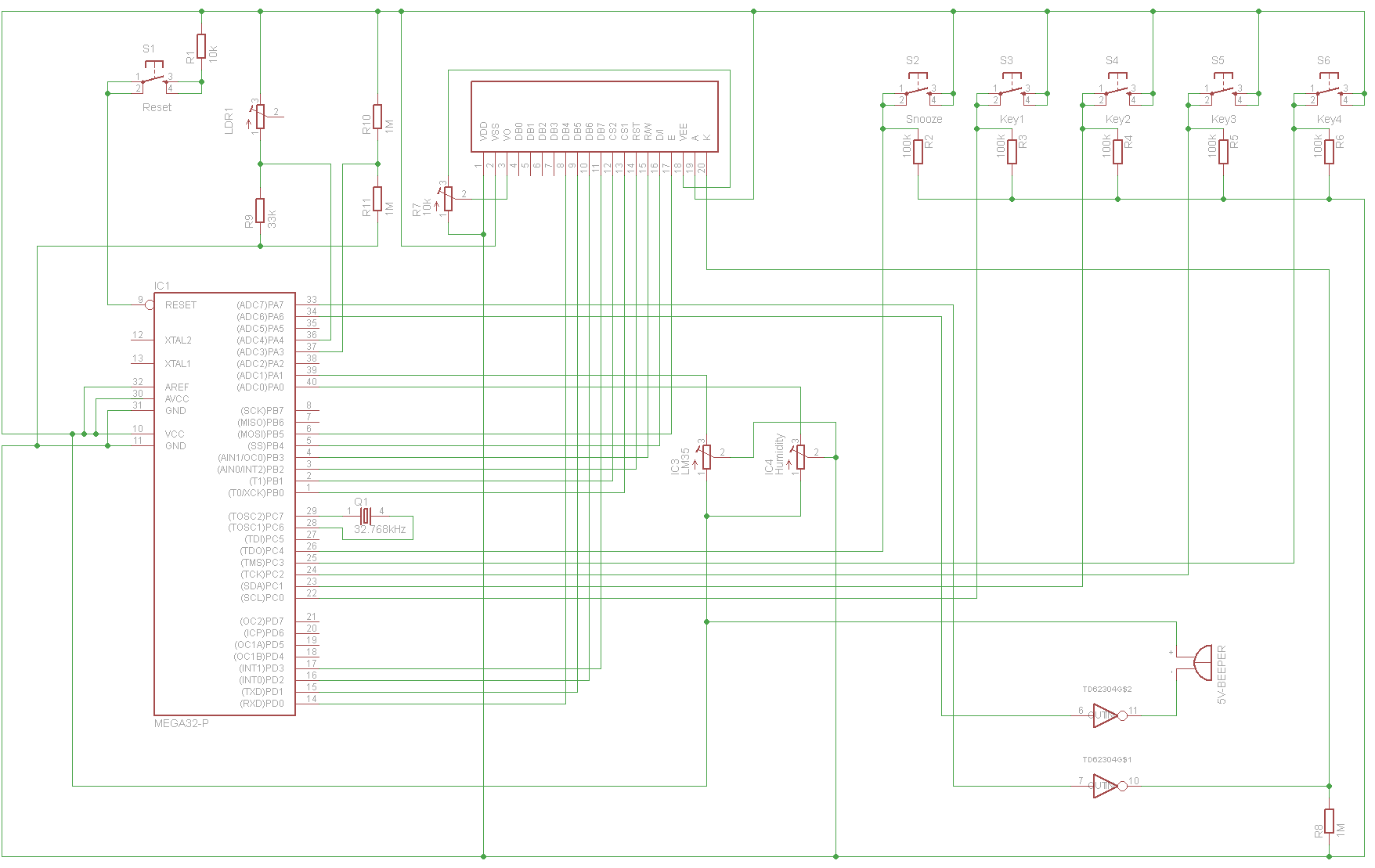
Below is a zip file containing an HTML version of the bascom code used and the .bgf graphics files for the numbers and icons, the Bascom code, the schematic in .png format and the schematic in Eagle layout format.