
AVR Based TIX Replica Clock
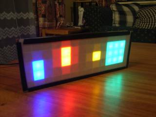
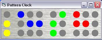
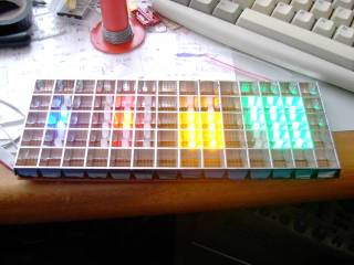
This is my second AVR project. I decided to make my own TIX clock using an AVR controller. The real TIX clock can be bought from places like Thinkgeek . When I first saw them I had to have one, but the price was a bit too high. And besides, it's much cooler and more fun to say "I made that!" So I started upon making my second clock project. Can you read the time in the picture above? It's 22:19. First thing I did was write a little Visual Basic simulator program to get a bit of an idea of what sort of code it would need. Below is a screen shot of that and it can be downloaded here.
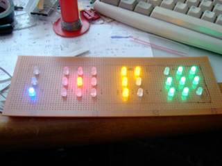
This project had it's own challenges. Origonally I wanted to have time adjustment done via a pulse encoder. So one could select the hours or minutes and then tweak them up or down using a little rotary knob. Unfortunatly, finding components like rotary encoders in little old New Zealand is a bit difficult, so I had to resort to 3 push buttons. Secondly the display had to be multiplexed as there is a total of 27 LED's in the display. Having all those LED's on at one time would draw great amounts of current plus also needing a great number of IO lines. I ended up multiplexing the display from left to right, so that there is never more than three LED's on at any time.
Here's a picture of the clock on the breadboard.
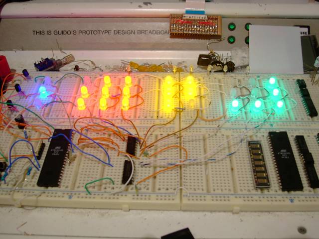
The chips in the bottom right had corner are just there for storage.
The display is made up out of Vero/strip board and that silver square stuff you see convering flourescent lights in offices. On top of that I have placed an opaque sheet of plastic film with a clear sheet of perspex on top to keep it all flat and looking nice.
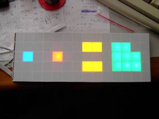
You can see its a lot easier to read once the grid and opaque sheet are in place.
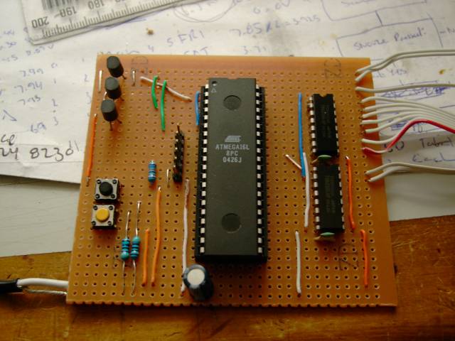
The controller board is a simple vero/strip board example as well, and mounted on the back of the display board. At the top left you can see the three transistors that are the row drivers, and on the right the two transistor array's that are the column drivers. The crystal for the RTC is mounted underneath the board.
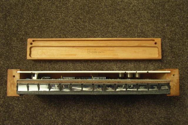
So that I could display it in the lounge I wanted the clock to sit in a nice wooden case. For this I got some Rimu batten into which I cut some grooves for the clock assembly to sit. Rimu is a New Zealand native tree and is used often to craft furniture. With this Rimu batten being only 40mm wide I ran into a space constriant problem by having a display board and a controller board. This prompted me to design and etch a custom board to house the LED's and controller on one board. I also added a wooden spacer between the PCB and the square grid to reduce the light hotspots a little bit when the LED's are on. I glued some silver foil to this to reflect more light out from behind the LED's.
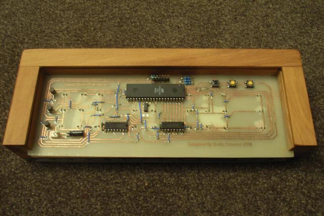
On the top left you can see the three controller buttons and in the middle the AVR with ISP connector above it.
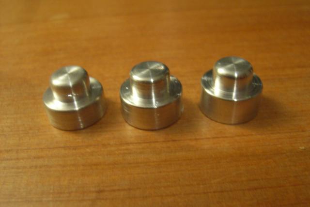
I turned up some custom aluminium buttons on the lathe which protrude through the rear panel allowing for adjustment. I also changed the clear perspex on the front to a smoked perspex to make it even better to see in daylight.
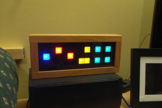
And sitting in the lounge doing its thing...